18. PLC Ladder Program | Example Explained with Diagram
In the programmable logic controller program, mostly the LD programming language is used.
Before writing PLC program in ladder diagram (LD) language, you should be familiar with some basic tips like-
- The basic concept of a logic gate in LD
- PLC Programming rules
- PLC programming Instructions
- PLC Instructions Address
Today I am sharing my article about the PLC ladder diagram program example. Explained in detail.
At the end of this tutorial, you will learn how to write PLC ladder program with a ladder diagram (LD).
Now, let’s start.
How to Write PLC Ladder Program using a Ladder Diagram?
It is always easier to understand PC programming with the help of example rather than tons of theory.
In the ladder diagram program, the switches are considering as inputs and load are considering as coil or output.
PLC Ladder Diagram Program Example for Running Motor:
Problem Statement: Write a program for a simple motor with the following conditions.
Condition:
Case 1: Following conditions should be satisfied to start a motor.
- Switch 1 is off and switches 2 is on.
- Switch 3 is on or switch 2 is off.
- Both switch 4 and switch 5 are on or switch 3 is off.
- Switch 6 is on or both switch 4 and switch 5 are off.
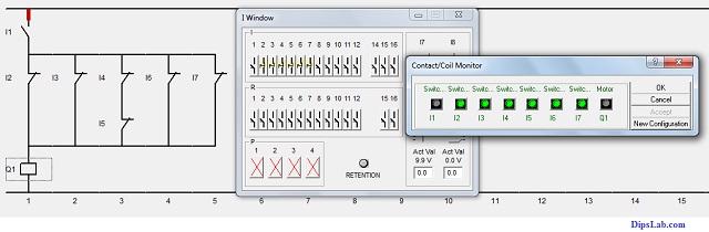
Case 2: Following conditions should be satisfied to stop a motor.
- Switch I1 is on.
Solution:
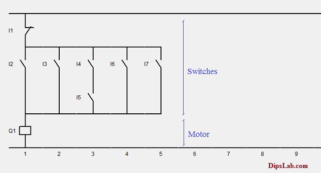
Now, we draw the ladder diagram program with seven switches and a single motor.
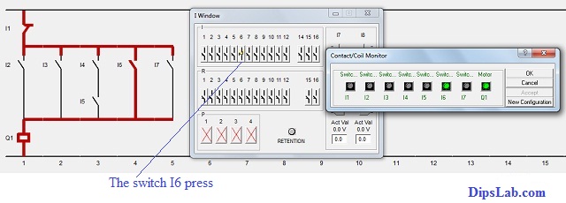
As per the below diagram, the switches are representing as I1, I2, I3, I4, I5, I6 and I7. And a coil of the motor is representing as Q1.
The conditions (i.e. On 0r Off modes) of the switches are operated by the toggle button.
First of all, all switches (I2, I3, …., I7) are Normally Open (NO) contact except switch I1.
Case 1: Motor in a Running Condition
Follow the conditions one by one as below.
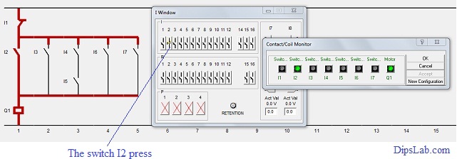
According to the first case, switch I1 has normally close contact.
When you press the switch I2, it gets close contact. This causes the power flowing through the circuit. And the motor starts running.
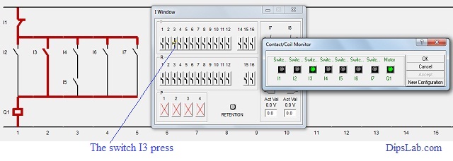
When the switch I3 is pressed and the switch I2 is realized then power flows through the circuit. This makes to run the motor continuously.
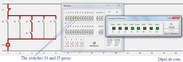
You can see, the switches I4 and I5 are connected in the series.
If both switches I4 and I5 are pressed then it makes the contact (NC) to flow the power. So the motor will run continuously.
To satisfy the last point in the first case, the switches I6 or I7 should be pressed.
After getting normally closed contact, power continuously flows through to the circuit. Due to this, the motor still runs.
Case 2: Motor in a Stop Condition
If the switch I1 is in NC contact, the switch I1 gets pressed.
Here the switch I1 is in series contact.
After the breaking contact, power will not flow to the motor. So, the motor will stop running.
That’s it all about PLC Ladder Diagram Program example. I have also explained how to write PLC ladder program with images.
What’s Next?
Let’s try to implement logic gates using PLC ladder programming. Logic gates are the most common utility functions in electrical and you will find it very useful in many of the PLC programming projects.
I hope that this article will be useful to learn the basic concept of PLC ladder programming.