Digital I/O and Analog I/O
Automation has become the backbone of almost all industries worldwide. Digital IO and analog IO are the most basic terms of any PLC/DCS based control and microcontroller-based applications.
A PLC collects data from the field, process it as pre-programmed and produces one or more outputs.
The data that is collected from the field is considered as the input to the PLC and the data passed from PLC to the field is considered as its output.
PLCs has sophisticated electronic blocks/cards for collecting these data and producing the outputs.
This article is meant to give you a basic idea on various types of inputs in PLC and the difference between them.

Digital IO and analog IO classification
Basically, PLC inputs and outputs are classified as follows:
- Digital Input – DI
- Digital Output – DO
- Analogue Input – AI
- Analogue output – AO
Apart from this, there are various other I/O types which are not discussed in this article.
Digital Input – DI

Digital inputs are binary inputs (0 or 1) that are applied to the PLC. Binary inputs are basically voltages, varying from 5V to 230V depending upon the type of card used. In simple words, any push-button, switches or sensors produces digital inputs to a PLC. Digital inputs are used to check the status of any devices whether it is ON or OFF. For an Input module of 24Vdc, 0Vdc acts as OFF state (Binary 0) and 24Vdc acts as ON state (Binary 1).
Digital Output

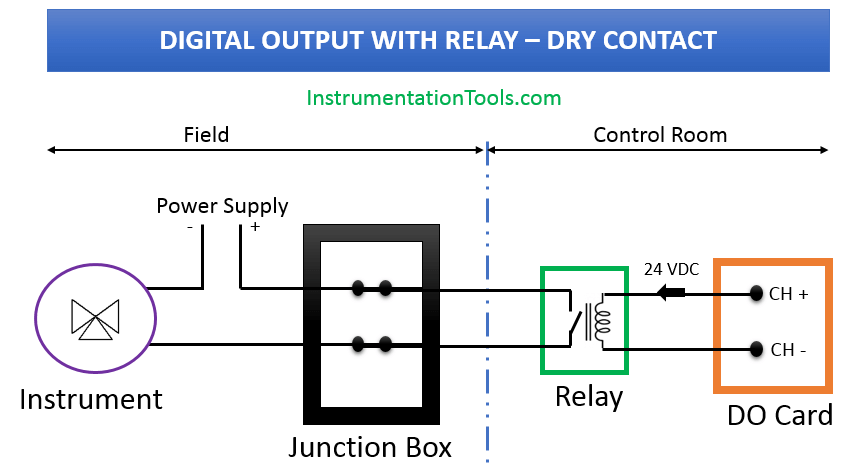
Digital outputs are binary outputs (0 or 1) from the PLC. It is a processed control output from the PLC to the field. It is used to ON or OFF any piece of field equipment. DO is like a contact of a relay when the preprogrammed conditions are satisfied the contacts are closed. DO can be used to operate solenoid valves, relays, indicating lamps or as a command to any other devices.
Analog Input – AI

Analog input is a continuous input from the field to the PLC. Unlike digital signals, is not a constant voltage signal. It can vary depending on the field conditions. The commonly used analogue signals are 4-20mA signal and 0-10Vdc Signal. Depending on the field conditions the input signal can vary between 4-20mA or 0-10Vdc. For Example, if you are monitoring a pressure of water flowing through a pipe using a pressure transmitter of range 0-10 Bar, the transmitter will give a signal between 0 and 10V proportional to the pressure in the pipe.
Analog Output

Analogue output is a continuous output from PLC to the field devices. For example, if you have a variable frequency drive and you want to give a speed reference signal to it you can use analogue output. Otherwise, if you are measuring the pressure using analogue input as explained above and you would like to display it on an analogue meter you can use an analogue output of PLC.
Difference between DI and AI
As explained above digital input and analogue input are data collected from the field. Digital input is binary in nature, either it can be ON or it can be OFF. Either it can be 0V or it can be 24V based on the type of IO module used. Switches, sensors etc. are examples of digital input. Analog signal is a time-varying signal. It can be varying between 0-10V or 0-20mA based on the design. Transduces are examples of analogue input devices.
Difference between DO and AO
A digital output is binary in nature, either it can be ON or it can be OFF. Either it can be 0V or it can be 24V based on the type of IO module used. Analog signal is a time-varying signal. It can be varying between 0-10V or 0-20mA based on the design.
One Reply to “Digital I/O and Analog I/O”
Comments are closed.