Cabling of MODBUS RTU – RS485 communication systems
In a MODBUS RTU over RS485 communication, we connect a MASTER device to one or more slave devices [MODBUS enabled solar inverters, electric meters, sensors etc.]
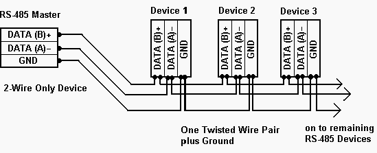
Rule 1: Connection Port
Each device [MASTER or SLAVE] has a connection port with 2 terminals that are used to communicate with that particular device over MODBUS RTU – RS485. These terminals are mostly marked as A [or DATA +] and B [or DATA -]. The cabling is done such that all these devices are connected in parallel. This means that all the A terminals should be connected together and all the B terminals should be connected together .
QUICK TIP- Reversing the ‘A’ and ‘B’ connections of a device can lead to NOT being able to communicate with that device. In many cases, the whole communication systems can stop working owing to the reverse polarity [voltage] found on the terminals of incorrectly connected device
In order to avoid this problem, it is recommended that the cable of same color should be used to connect all A terminals together and similarly cable of same color [but different that the color used for A] to be used to connect all B terminals together.

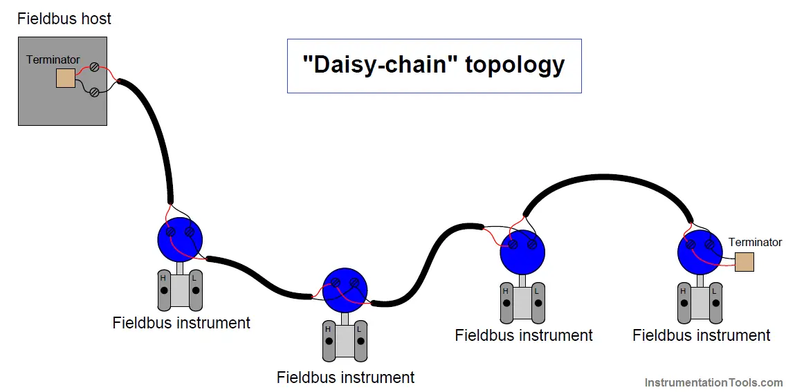
Rule 2: Connection between the devices
The easiest and the best way to connect the devices in a MODBUS RTU – RS485 communication is using DAISY CHAIN method. It is shown below. Any other way of connecting the devices together is not recommended as it might cause communication issues or damage to the overall system.
Rule 3: Maximum distances and number of slaves
The maximum length of the communication cable should be no longer than 800m [recommended].The maximum number of devices that can be connected over this network can be 32[for Modbus RTU], including the master device [TrackSo data logger in our case]
Rule 4: Terminal Resistances
In order to avoid signal reflections, it is required to turn on the 120 ohm terminal resistance at ends of the communication cable. In our case, we are required to turn ON the terminal resister of the last device [inverter or meter]. In some cases, it is also required to turn ON the terminal resister of the first device [inverter or meter].
Rule 5: Grounding
For MODBUS communications, Properly grounding your instrument is important, especially when working close to high voltage sources such as PV arrays. An instrument that is not appropriately grounded can give false readings, fail completely or turn into a safety hazard
QUICK TIP-If you are encountering noise or irregular or abnormal problems with a Modbus serial link, the problem is likely related to grounding, incorrect shielding, or wiring power wires next to Modbus wiring.
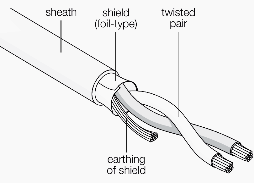
Rule 6: Type of cables to use
For MODBUS communications, a shielded and twisted pair cable is used. One example of such cable is Belden 3105A. But any cable with similar characteristics can be used to connect all the devices together. The shielding can be of 2 types: braided [like a mesh of thin conducting wires] or like a foil [consiting of a thin sheet of metal covering the twisted wires]. Both types of shielding are OK.
QUICK TIP- This arrangement improves immunity to electromagnetic disturbances because the cable forms a series of successive coils, each of which faces in the opposite direction to the next one: in this manner any magnetic field in the environment traverses each pair of coils in opposite directions and its effect is thus very reduced (theoretically, the effect on each coil is exactly the opposite of the effect on the next one and thus the effect is cancelled).
Wiring characteristics
- 0.22–0.5 mm2 for runs up to 300 meters
- 0.5–0.75 mm2 for runs up to 1200 meters
- Characteristic impedance: 120 Ohm +/- 10%;
- Use Shielded twisted-pair cable if the bus cable exceeds 3m.
- Each shield must be grounded at one side only
- Overvoltage/overcurrent transient protection should be provided