Wiring Diagrams of PLC and DCS Systems – DI, DO, AI, AO
In this article, we will learn the basic concepts of PLC and DCS control systems Wiring Diagrams for Digital Input (DI), Digital Output (DO), Analog Input (AI), and Analog Output (AO) signals.
Keep in mind that these diagrams are without a Barrier or isolator, fuses, and surge protector for keeping it very simple and understandable.
Also Check: Analog and Digital I/O
Wiring Diagrams of PLC and DCS
The below list shows the basic types of wiring connections available for DI, DO, AI, AO Signals:
Digital Input (DI) Signals
- Single-wire Connection
- Two-wire connection
- Two-wire connection with Line Monitoring
- DI with Relay – Wet Contact
- DI with Relay – Dry Contact
Digital Output (DO) Signals
- Two-wire connection
- DO with Relay – Wet Contact
- DO with Relay – Dry Contact
- Interfacing with Other Control Systems
- DO with Line Monitoring
Analog Input (AI) Signals
- Single-wire connection
- Two-wire connection
- Three-wire connection
- Interfacing with other control systems
Analog Output (AO) Signals
- Two-wire connection
Digital Input Signals to PLC / DCS
Input type with respect to system
Terminal type/connection, Shield is not shown for simplicity.
Two-Wire Connection with Input Card
The two-wire connection is used to connect field instruments like limit switches, proximity switches, motor run feedback, Pump start permissive, etc.
Two-Wire Connection with Line Monitoring

When we need additional protection measures to identify the short circuit and open circuit of digital inputs then we use this configuration.
Generally, a pair of resistors are used at the terminations of field instruments or in some cases at marshalling cabinets.
This works on the principle of change in resistance. During the Open circuit, both resistors R1 & R2 in line, so we will get some loop resistance, say “x” ohms. During Short Circuit, resistor R1 becomes zero and we will get some other loop resistance, say “y” ohms.
The input cards are designed such that it will identify the signal status and differentiates these conditions, alerts the system engineers with alarms.
DI Card with Single Wire Connection

DI With Relay – Wet Contact (For Coil)

This configuration is used when we need an additional power supply for the field instruments, motor control centers, etc.
Generally, in marshalling cabinets, we make the necessary wiring arrangements as per the application requirements.
We are using the additional power supply in the marshallaling cabinet (or at the control room side), so we are calling this a WET Contact.
When the field instrument is in Open state then the relay will not be energized thus DI card doesn’t have the return signal, so it will consider as OFF state.
When the field instrument is in Close state then the relay will be energized thus DI card has the return signal, so it will consider as ON state.
This external relay power supply called as interrogation voltage.
The interrogation voltage from the panel can be 24 VDC, 110VDC, etc.
What is the Interrogation Voltage?
Interrogation voltage is a term used in relation to digital inputs of PLC or DCS control systems.
When there is some activity in the digital inputs like limit switch activation, then there will be a change in input state from open to close or close to open depends on the type of contact used in the limit switch.
Now we need to interrogate (identify) the state of these contacts (open/close) using a voltage. So we send a voltage (12VDC, 24VDC, 110 VDC, etc) to the limit switch and receives the signal back when the limit switch is in close state.
The PLC reads these signals and takes the action as per its logic. This voltage is called as interrogation voltage.
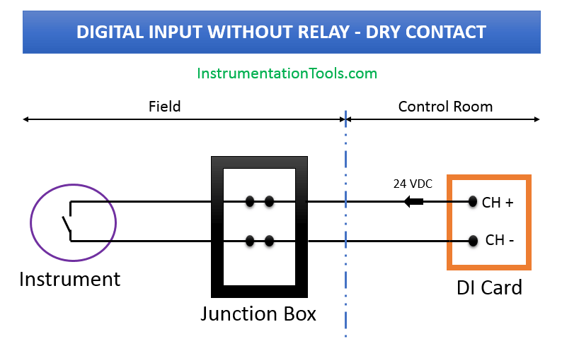
DI With Relay – Dry Contact (For Coil)
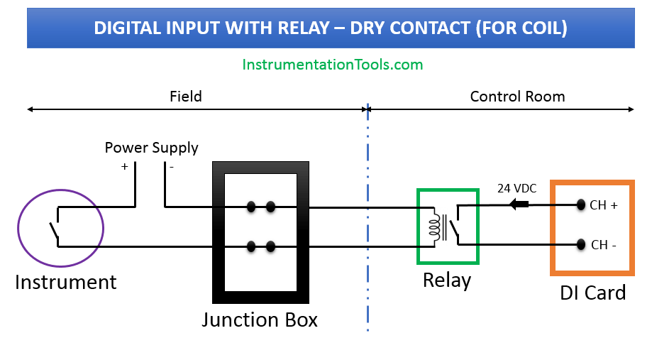
We are NOT using any additional power supply in the marshallaling cabinet (or at control room side), so we are calling this a DRY Contact.
When the field instrument is in Open state then the relay will not be energized thus DI card don’t have the return signal, so it will consider as OFF state.
When the field instrument is in Close state then the relay will be energized thus DI card have the return signal, so it will consider as ON state.
Example: Motor Run Feedback.
The interrogation voltage from voltage can be 24 VDC, 110 VDC, etc.
Digital Output Signals from PLC / DCS
Output type with respect to system terminal type/connection.
The shield is not shown for simplicity reason.
Two-wire connection with Output Card

This configuration is used to control the digital instruments like Solenoid Valves.
We may use Barriers after the DO card for safety reasons. Barriers are not shown in the diagrams.
When the DO command is given then the respective voltage will go the field instrument and it will be energized.
When the DO command is taken back then the respective voltage will be stopped to the field instrument and it will be De-energized.
DO With Relay – Wet Contact

We use an additional power supply (24 VDC, 110 VDC, 230 VAC, etc) in the marshalling cabinet (at the control room side) to power the field instrument.
This configuration generally used for hooters, beacons, high-power solenoid valves, etc.
DO With Relay – Dry Contact

This configuration generally not preferred.
Interfacing with Other Control Systems (DCS/PLC/ESD)
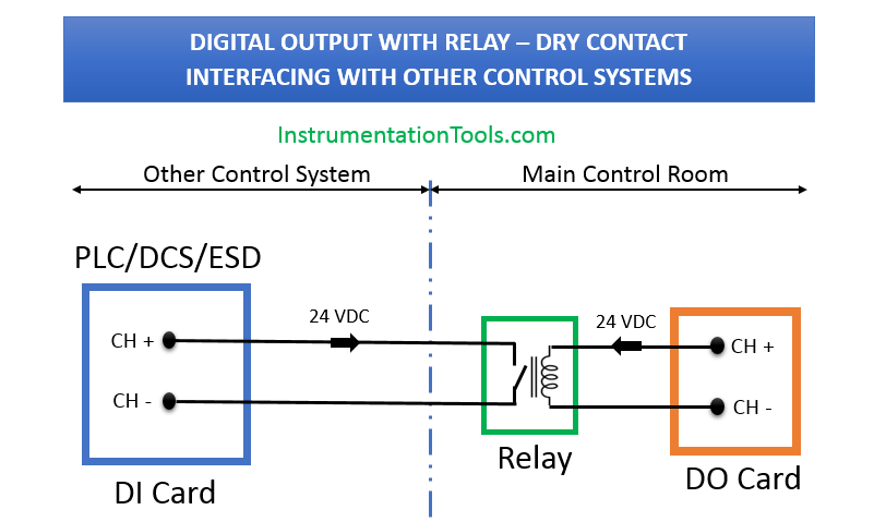
This configuration widely used in industries for interfacing with third-party control systems.
DO with Line Monitoring
The line monitoring for digital output cards also possible but up to relay coil and/or up to field shall be confirmed by the system vendor.
Analog Input Signals to PLC / DCS
Shields are not shown for simplicity reasons.
The 4-wire instruments require an additional power supply.
Two-wire Connection with AI Card

This configuration is used to connect two-wire transmitters like PT, TT, FT, LT, etc.
We may use barriers also after the AI card for safety precautions. These are not shown in the diagrams.
AI Card with Single Wire Connection

For Interfacing with Other Control Systems
DCS AO to PLC AI
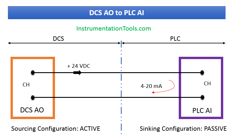
Both side’s Active will not work.
PLC AO to DCS AI
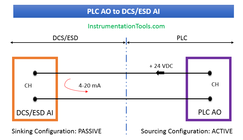
Both sides Active will not work
Both sides Passive will not work.
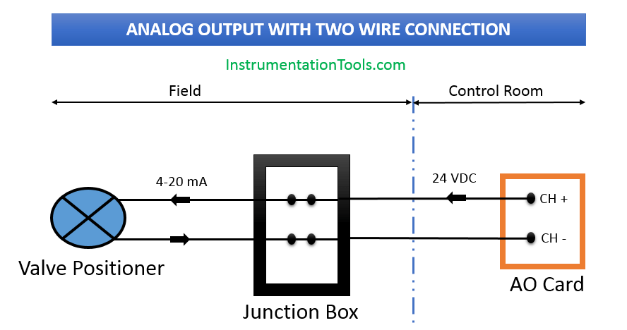
Analog Output Signals
Join the Discussion! Share your thoughts about the basic wiring diagrams using the comments section.
Missed any?
If you liked this article, then please subscribe to our YouTube Channel for PLC and SCADA video tutorials.
You can also follow us on Facebook and Twitter to receive daily updates.