01. PLC Basics| Block Diagram| Types| Advantages and Disadvantages | Part-1
Programmable Logic Controller is a short abbreviation of PLC. PLC is basically known as ‘Primary Controller‘ or ‘Programmable Controller’.
In the enhancing mode and development of new technologies, the trend of PLC is evolving. It has become an integral part of the control system in an industrial environment.
What exactly is the Programmable Logic Controller [PLC]?
In this tutorial, I am describing the PLC in detail. Read this complete tutorial to learn PLC basics. I am explaining the working of PLC and its different types.
At the end of this article, you will find many of the day-to-day applications you can automate with PLC.
This is really interesting. Right?
Let’s start then…
What is the Programmable Logic Controller (PLC)?
PLC is a solid-state control device or computerized industrial controller that performs discrete or sequential logic in the factory or automation environment.
If you get this definition completely or not, don’t worry. In this article, I will be explaining each of the terms mentioned this definition.
Basically, PLC is a combination of software and hardware. It acts as the brain of the machine or system for automation control systems.
Technical Definition of PLC:
The programmable logic controller is defined by ‘National Electrical Manufacture Associations [NEMA]’ as,
The digital electronic device that uses programmable memory to store instructions and implement specific function such as programming logic, sequence, timing, counting and arithmetic operations to control electronic machines and technical process.
This is how the Mini PLC looks like.
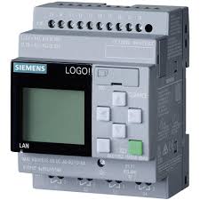
The PLC controller devices can be executed or operated by automatically and manually. For its operation, it consumes additional manpower, time, utility, and accurate operation in the system.
The most benefit of PLC:
It performs precise operations within very less time. And it consists of many components for controlling devices.
To understand the different operations performed by PLC, I am explaining each useful PLC component with the help of a block diagram in detail.
Basic Block Diagram of PLC System
The block diagram of PLC consists of different components. Each component has associated specific functions and operations in the PLC.
The list of basic components are.
- Input and Output Modules
- Power Supply
- Control Processing Unit (CPU)
- Memory System
- Communication Protocols
- Programming
You can see all these above PLC components in the below figure.
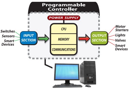
Let’s see the description of the system one-by-one (PLC basics briefly explained).
1.Input and Output (I/O) Modules
The input/output modules in PLC are of two types. It can be either digital or analog.
Just like any other device or machine, we have to provide input to the PLC controller. It yields output.
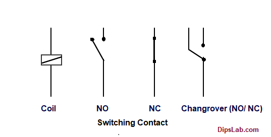
For example, when the user presses a button, the motor starts. Here the switch button is input. The motor is an output device.
In PLC, to take the input and to return the output, there are an I/O modules.
The input modules are used for providing an interface for input devices like different types of switches (push button switch, selector switch, limited switch), sensors, etc.
The output modules are used for providing an interface for output devices like motor, fan, relay, light, lamp, electric heater, solenoid valve, buzzer, etc.
You can learn PLC input and output modules in detail.
2. Power Supply
There is no science to make the electrical device works without providing a power supply.
Every device operates around you need power whether if its electrical or mechanical or any other power supply.
For PLC, we need an electrical power supply.
The power supply provides power to all other components to operates. It provides power to the input/output modules, memory system, and processor.
The function of the power supply is to provide the DC or AC power to operate the PLC.
How much power does it require to operate PLC?
Most of the PLCs work at 220VAC or 24VDC. You can learn the difference between AC and DC in detail.
3. Central Processing Unit (CPU)
Central Processing Unit is the heart of the PLC system. The function of the CPU is to store and run the PLC software programs.
It helps to perform the basic arithmetic, logic, controlling, and input/output operations specified by the instructions. It consists of the three subparts as memory, processor and power supply.
4. Memory System
A memory system is responsible for storing and retrieving data and information. It consist of different type of memory such as RAM, ROM, EEPROM and Flash memory.
Overall memory is classified into four sections based on the types of data it stores.
- Input/output Image Memory
- Data Memory
- User Memory
- Executive Memory
5. Communication Protocols
The communication protocols are useful for exchanging the information or data between connected devices through a network.
For further detail, kindly check topmost 10 communication protocols used in PLC.
6. PLC Programming
You need PLC programming instructions and programming to live the communication between different circuits of the PLC.
The useful information or data are communicated by the specific communication protocols.
Most of the PLC programmer works on the ladder diagram programming language. It is pretty easy as compared to other PLC programming languages.
How does Programmable Logic Controller Work?
The most important working principle is- the PLC is operated by continuously scanning programs. Scanning happens every time per millisecond. So, it is called as the Scan Cycle.
For this scan cycle, PLC required a little amount of time in the range of milliseconds or ms.
What are the basic PLC Scan Cycle?
The scan cycle consists of the following three basic main steps.
- Read the inputs
- Execute the program by the CPU
- Update the output
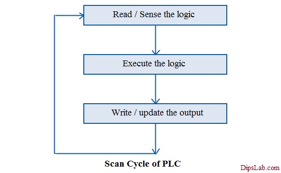
Step 1: Read / Sense the input
Firstly, PLC reads the on/off status of the external input signals. After scanning the input, it gets stored in the input memory. This input included switches, pushbuttons, proximity sensors, limit switches, pressure switches, etc.
Step 2: Execute the logic by the processor
This scanned input gets transferred to the CPU for processing from input memory. The processor executes the programming instructions based on the input. After the execution, the result (on/off) will be stored in the device memory.
Step 3: Update / write the output:
When the program executes the last instruction, it will send the on/off status to the output device memory. The outputs include solenoids, valves, motors, actuators, and pumps.
All three steps get completed under the scan time.
What is Scan Time?
The amount of time is taken by the processor to read/sense the first input and execute the last output called the Scan time.
PLC is so fast as it can easily scan and execute the program in few milliseconds i.e. 10-15 milliseconds.
What are the Types of Programmable Logic Controller (PLC)?
Two types of PLCs are used for commercial or industrial purposes.
- Compact PLC
- Modular PLC
Knowing these two types is the part of PLC basics knowledge.
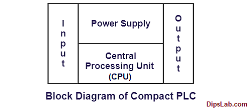
What is a Compact PLC?
It is also called as Integrated PLC or Fixed PLC.
The compact PLC has a fixed number of input/output modules along with power supply and CPU.
What is a Modular PLC?
It consists of a variable number of inputs and outputs. Inputs and outputs can be added to the modular PLC systems by the user.
If you look at the below PLC designing structure, it looks more like a rack. So, it is also called as Rack-Mounted PLC.

I have explained both compact and Modular PLCs in detail. Check the difference between modular and compact PLC.
What are the Most Popular PLC Programming Languages?
Based on the International Electrotechnical Commission(IEC) standard, PLC programming languages are classified into five main standards.
- Ladder diagram (LD)
- Instruction List (IL)
- Structured Text (ST)
- Function Block Diagram (FBD)
- Sequential Function Charts (SFC)
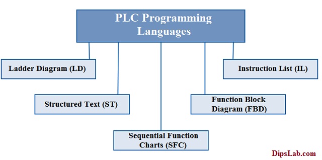
These are the topmost 5 different type of PLC programming languages.
According to the study and operations, ladder diagram (LD) is the widely PLC language for writing easily understandable programming logic. This programming logic based on the logic gates.
LD has a graphical user interface. It comes with many features that give an edge over other programming languages.
What is the most popular PLC brand used?
In the automation environment, more companies are manufacturing and working on the control system by using PLC and SCADA.
Today, there are multiple brands available for PLC systems. The Asea Brown Boveri (ABB), Allen Bradley (AB), General Electric (GE), Siemens, Delta, Mitsubishi, Omron, and Schneider are some of the very popular PLC brands.
Based on the usage, Siemens PLC tops the position. Allen Bradley PLC is at the second position in Automation.
You can use any brand of PLC as per your project requirements, study, and industry need.
What are the Applications of PLC?
For automation, multiple PLCs are used to monitor and control building systems in production processes.
PLCs are used in various industries like the steel industry, glass industry, cement industry, paper mill, coal mine, automobile industry, chemical industry, textile industry, robotic system, and food processing system.
In this PLC basics, I have already listed popular applications of PLC in industrial automation companies.
What are the Advantages and Disadvantages of PLC?
In an earlier article, I have explained the top 25 advantages and disadvantages of PLC over the relay system.
Lean more about: PLC vs Relay system
This is all about the Programmable Logic Controller aka PLC. In this article, I tried to cover all the PLC basics required.
If you have any queries, please hit your queries in the comment section. I will reply as soon as possible.
Programmable Logic Controller (PLC) Related Topics:
- PLC Automation Companies
- PLC Interview Questions and Answers
- PLC Based Automation Projects
- PLC Automation Training Institutes
Happy PLC Programming!