09. Rules for PLC Ladder Diagram Programming | Explained with Diagram
If you want to excel in Programmable Logic Controller (PLC) programming, then you should know about the rules used in PLC programming.
The different rules are applicable to the different types of PLC programming languages.
Especially, I am explaining these rules for PLC Ladder Diagram programming language with the representation of a ladder language program in PLC.
These rules will helpful for writing the PLC programs.
6 Rules for PLC Ladder Diagram Programming
Let’s start and follow these PLC programming rules on the based of digital inputs and outputs contact.
Here, you can see the LD program with input (NO and NC) and output contact.
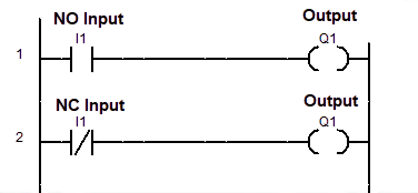
As per your program, you can arrange programming I/O instructions with the help of different programming rules.
1. Inputs can be used in Series as well as Parallel to form a connection
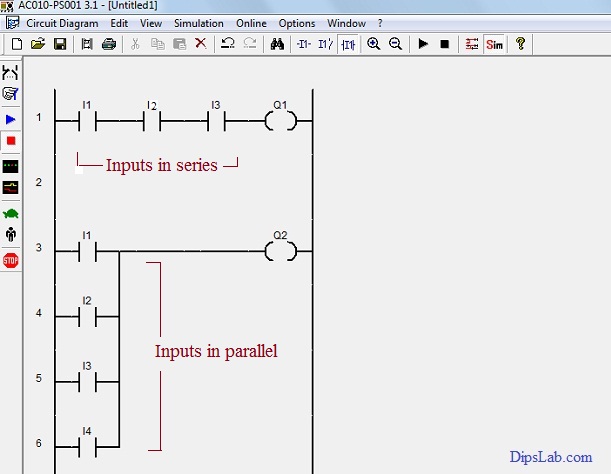
The number of inputs (I1, I2, I3, I4, ……In) can link with different outputs (Q1, Q2,…..Qn) by using series or parallel connection.
In the below figure, the three Inputs (I1, I2, and I3) are connecting in series and four Inputs (I1, I2, I3 and I4) are connecting in parallel with the Single output (Q1 and Q2) respectively.
So we can connect the inputs in series or parallel as per our programming requirement.
Note: In the program, AND gate follows the series connections and OR gate follows the parallel connection. For detail, do read logic gates in PLC ladder programming.
2. Outputs (or coil) can be used only in Parallel
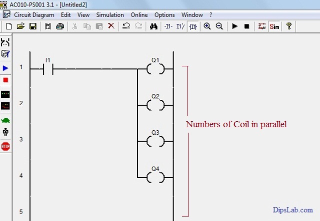
According to the second rule, outputs (Q1, Q2, Q3, Q4, ……Qn) are connected in parallel along with the single input (I1). Refer to the image below.
If the single input (I1) is normally closed (NC contact) then all outputs (Q1, Q2, Q3, Q4,….Qn) will be activated (On).
3. One Input can be used in multiple times in one program
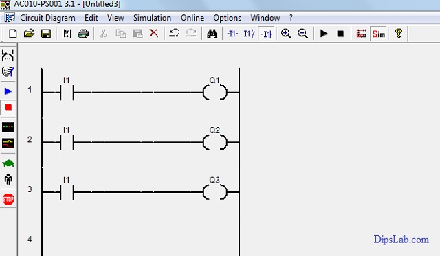
As per the third rule, a single input can be used to repeatedly in the different rungs.
From the below image, the program has different outputs but the same input (switch) connected.
4. One Output cannot be used multiple times in one program, except in Set/Reset and Latch/ Unlatch functions
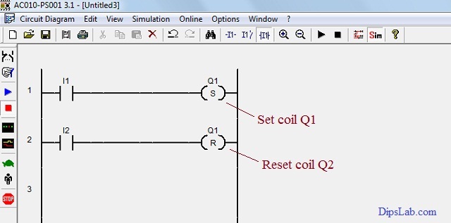
In the function set/reset, the same output address is used. And it can be connected to the same or different inputs.
As per the below image, different inputs (I1 and I2) are linked with the single output (Q1) using the set and reset function.
When the Input (I1) is pressed, the output coil will be set ( i.e. Q1 on activate mode). And when the input (I2) is pressed, the output coil will be reset ( i.e. Q1 on deactivate mode).
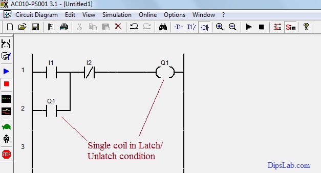
In latch/unlatch function, working is the same as set/reset function. The only difference is, the first input (I1) is normally opened (NO) and the second input (I2) is normally closed (NC).
The lanch/unlatch function is useful for the cycling process.
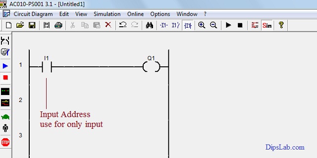
5. Input Address cannot be used as an Output Address
The same input address can be used as multiple inputs. And it can not be used as output.
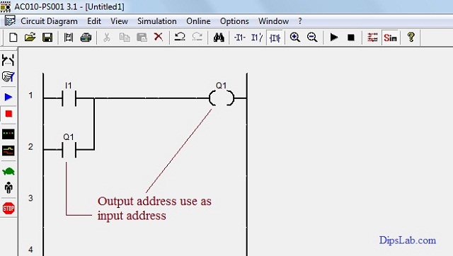
6. Outputs Address can be used as Inputs Address
The last rule is for the cycling process (i.e. process continuous from start to end).
In the image below, the output coil works as the input coil with the use of latch/unlatch function.
So, you can write the PLC program in different ways by using the multiple PLC programming instructions.
That’s it all!
Surely, you will find these rules for PLC ladder diagram programming useful when you start actually working on PLC programming.
Make a practice of following these rules and writing the PLC programs as per your requirements by using the logic gate programming concept.