Wheatstone bridge
In analog electronics, we come across various signals, some of them are measured by changes in resistance and some of them are with changes in inductance and capacitance.
If we consider the resistance, most of the industrial sensors like temperature, strain, humidity, displacement, liquid level, etc. produces the change in value of the resistance for an equivalent change in the respective quantity. Therefore, there is a need for a signal conditioning for every resistance based sensor.
For example, the simplest device we can think of is the Light Dependent Resistor or LDR. As the name suggests, an LDR is a device, whose resistance changes according to the amount of light falling on it.
Generally, the resistance measurement is divided into three types:
- Low Resistance Measurement
- Medium Resistance Measurement
- High Resistance Measurement
If the resistance measurement is possibly from a few micro ohms to milli ohms, then it is considered as a low resistance measurement. This measurement is actually used for research purpose. If the measurement is from 1 ohm to few hundreds of KΩ is generally referred as a medium resistance measurement. Measurement of normal resistors, potentiometers, thermistors, etc. comes under this category.
And very high resistance measurement is considered from few Mega Ohms to greater than 100 Mega Ohms. For finding the medium value of the resistance different methods are used, but mostly Wheatstone bridge is used.
What is Wheatstone bridge
Bridge Networks or Circuits are one of the most popular and popular electrical tools, often used in measurement circuits, transducer circuits, switching circuits and also in oscillators.
A Wheatstone bridge is an diamond shaped electrical circuit / bridge network used to measure an unknown electrical resistance values by balancing two legs of a bridge circuit, one leg of which includes the unknown component.
The primary benefit of the circuit is its ability to provide extremely accurate measurements (in contrast with something like a simple voltage divider).
Its operation is similar to the original potentiometer.
The Wheatstone Bridge circuit is nothing more than two simple series-parallel arrangements of resistances connected between a voltage supply terminal and ground producing zero voltage difference between the two parallel branches when balanced. A Wheatstone bridge circuit has two input terminals and two output terminals consisting of four resistors configured in a familiar diamond-like arrangement as shown. This is typical of how the Wheatstone bridge is drawn.

History of Wheatstone bridge
The Wheatstone bridge was invented by Samuel Hunter Christie (sometimes spelled “Christy”) in 1833 and improved and popularized by Sir Charles Wheatstone in 1843. One of the Wheatstone bridge’s initial uses was for soils analysis and comparison.
Working Principle of Wheatstone bridge
Wheatstone Bridge is used in applications where small changes in resistance are to be measured in sensors. This is used to convert a change in resistance to a change in voltage of a transducer. The combination of this bridge with operational amplifier is used extensively in industries for various transducers and sensors.
For example, the resistance of a Thermistor changes when it is subjected to change in temperature. Likewise, a strain gauge, when subjected to pressure, force or displacement, its resistance changes. Depending on the type of application, the Wheatstone Bridge can be operated either in a Balanced condition or an Unbalanced condition.
A Wheatstone bridge consists of four resistors (R1, R2, R3 and R4) that are connected in the shape of a diamond with the DC supply source connected across the top and bottom points (C and D in the circuit) of the diamond and the output is taken across the other two ends (A and B in the circuit).
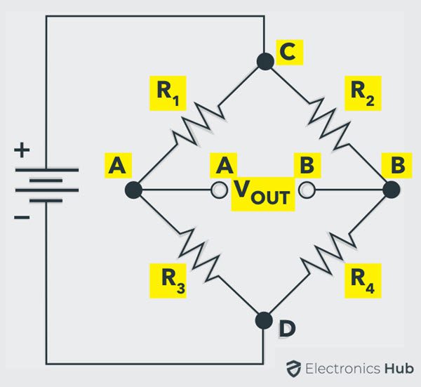
This bridge is used to find the unknown resistance very precisely by comparing it with a known value of resistances.
In this bridge, a Null or Balanced condition is used to find the unknown resistance.
For this bridge to be in a Balanced Condition, the output voltage at points A and B must be equal to 0. From the above circuit:
The Bridge is in Balanced Condition if:
VOUT = 0 V
To simplify the analysis of the above circuit, let us redraw it as follows:
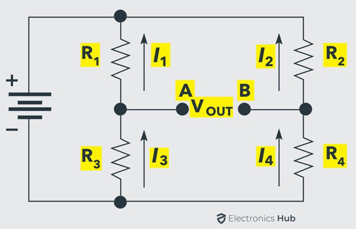
Now, for Balanced Condition, the voltage across the resistors R1 and R2 is equal. If V1 is the voltage across R1 and V2 is the voltage across R2, then:
V1 = V2
Similarly, the voltage across resistors R3 (let us call it V3) and R4 ( let us call it V4) are also equal. So,
V3 = V4
The ratios of the voltage can be written as:
V1 / V3 = V2 / V4
From Ohm’s law, we get:
I1 R1 / I3 R3 = I2 R2 / I4 R4
Since I1 = I3 and I2 = I4, we get:
R1 / R3 = R2 / R4
From the above equation, if we know the values of three resistors, we can easily calculate the resistance of the fourth resistor.
Alternative Way to Calculate Resistors
From the redrawn circuit, if VIN is the input voltage, then the voltage at point A is:
VIN ( R3 / (R1 + R3))
Similarly, the voltage at point B is:
VIN ( R4 / (R2 + R4))
For the Bridge to be Balanced, VOUT = 0. But we know that VOUT = VA – VB .
So, in Balanced Bridge Condition,
VA = VB
Using above equations, we get:
VIN ( R3 / (R1 + R3)) = VIN ( R4 / (R2 + R4))
After simple manipulation of the above equation, we get:
R1 / R3 = R2 / R4
From the above equation, if R1 is an unknown resistor, its value can be calculated from the known values of R2, R3 and R4. Generally, the unknown value is called as RX and of the three known resistances, one resistor (mostly R3 in the above circuit) is usually a variable Resistor called as RV.